SolidWorks Simulation - Avoiding Singularities
There is document - SolidWorks Simulation - Avoiding Singularities available here for reading and downloading. Use the download button below or simple online reader.
The file extension - PDF and ranks to the Presentations category.

381
views
Tags
Related
Comments
Log in to leave a message!
Description
Download SolidWorks Simulation - Avoiding Singularities
Transcripts
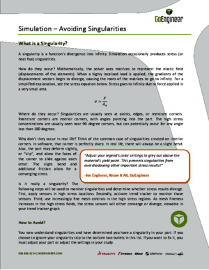
8886883234 | GOENGINEERCOM “Adjust your legend’s color settings to grey out above the material’s yield point This prevents singularities from overshadowing other important stress results!” -Joe Engineer, Know It All, GoEngineer Simulation – Avoiding Singularities What is a Singularity? A singularity is a function’s diver gence into infinity Simulation occasionally produces stress (or heat flux) singularities How do they occur? Mathematically, the solver uses matrices to represent the elastic field (displacements of the elements) When a highly localized load is applied, the gradients of the displacement vectors begin to diverge, causing the roots of the matrices to go to infinity For a simplified explanation, see the stress equation below Stress goes to infinity due to force applied in a very small area Where do they occur? Singularities are usually seen at points, edges, or reentrant corners Reentrant corners are interior corners, with angles pointing into the part The high stress concentrations are usually seen near 90 degree corners, but can potentially occur for any angle less than 180 degrees Why don’t they occur in real life? Think of the common case of singularities created on interior corners In software, that corner is perfectly sharp In real life, there will always be a slight bend Also, the part may deform slightly, or “slip”, and allow the faces of the corner to slide against each other The slight bend and additional friction allow for a converging stress Is it really a singularity? The following steps will be used to monitor singularities and determine whether stress results diverge First, apply sensors in high stress locations Secondly, activate trend tracker to monitor those sensors Third, use increasingly fine mesh controls in the high stress regions As mesh fineness increases in the high stress fields, the stress sensors will either converge or diverge, viewable in your trend tracker graph How to Avoid? You now understand singularities and have determined you have a singularity in your part If you choose to ignore your singularity skip to the bottom two bullets in this list If you want to fix it, you must adjust your part or adjust the settings in your study 8886883234 | GOENGINEERCOM Adjust Geometry Locate reentrant corners where singularities most commonly occur Since the force transfer trying to go through that edge is causing the singularity, provide a larger surface area in order to distribute the loads Fillets or chamfers are commonly used The pictures below demonstrate this concept Figure 1 Re-entrant corner vs Fillet Don’t let the fear of singularities prevent you from defeaturing your models Remember, sometimes fillets are useful, but they always cause a finer mesh and longer calculation times If non-filleted re-entrant corners are unavoidable in your part, design nearby support to prevent crack growth This support must dissipate the load over a larger surface area before allowing the load to affect the reentrant corner Adjust Fixtures A fixture applied at a point or edge can cause a singularity To understand why, consider a simple cantilever beam problem The force being applied on one end of the beam must be counteracted by the fixed end If the element along the edge of the beam is forced to remain rigid while simultaneously counteracting the force, a singularity is created In this situation, applying the fixture to the face rather than the edge will prevent divergence If fixing the face is not applicable, include the component from the assembly that is creating the fixture A fraction of the component may also be used as long as it is large enough to allow for complete load transfer Only replace components with fixtures if the component is much stiffer than the study’ s part, or if the fixtures are far removed from important results 8886883234 | GOENGINEERCOM Figure 2 Fixture on edge Realize that some connectors act as fixtures too Check if your connector is assuming infinite stiffness by accessing the Solidworks Help menu If so, adjust your connectors or include the modeled part in the study The assembly shown below is connected by a tight-fit bolt connector The tight fit allows the shank to deform, but the nut is still infinitely stiff The actual bolt needs to be modeled Figure 3 Singularity due to Connector Adjust loads Don’t apply force or a heat source at points or small edges This causes a sharp inflection point in the data input into the deflection equations, which leads to the singularity If a thin loading area is required, create split lines and apply force to the area between them, as in the picture below This will allow convergence
Recommended