ra_92003.pdf
There is document - ra_92003.pdf available here for reading and downloading. Use the download button below or simple online reader.
The file extension - PDF and ranks to the Documents category.

373
views
Tags
Related
Comments
Log in to leave a message!
Description
RA 92003/0196 Variable Displacement Pump AA4VG Series 3, for Closed Circuits Axial Piston, Swashplate Design Size 28250 Nominal Pressure 5800 psi Peak Pressure 6500 psi RA 92003/0196 Replaces: 0895 See Appendix for Sizes 28 and 250 The AA4VG is a swashplate design, variable displacement axial piston pump specifically designed for hydrostatic closed circuit transmissions The design incorporates a charge pump, charge pressure relief valve, two combination high-pressure relief/anti-ca
Transcripts
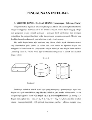
RA 92003/0196 1 Nominal Pressure 5800 psiPeak Pressure 6500 psiSize 28250 Variable Displacement Pump AA4VG Series 3, for Closed CircuitsAxial Piston, Swashplate Design RA92003/0196 The AA4VG is a swashplate design, variable displace-ment axial piston pump specifically designed forhydrostatic closed circuit transmissions The designincorporates a charge pump, charge pressure reliefvalve, two combination high-pressure relief/anti-cavita-tion check valves, and integral Pressure Cut-OffFlow is proportional to drive speed and pump displace-ment and is infinitely adjustable It increases withincreasing swashplate angle from zero to its maximumvalue Swiveling the pump over center smoothlyreverses the direction of oil flowA complete range of modular control and regulatingdevices is availableThe pump is available with a full range of through driveoptions and tandem pump configurations Replaces: 0895 See Appendix forSizes 28 and 250 Variable Displacement Pump AA4VG, Series 3 RA92003/0895 2-3 Ordering Code Hydraulic Fluid Petroleum Oil (For operation with other fluids, consult a Rexroth Application Engineer) Axial Piston Unit Variable swashplate design Nominal pressure 5800 psi; peak pressure 6500 psi AA4VMode of Operation Pump in closed circuit GSize ≈ Displacement V gmax (cm 3 ) 2840567190125180250 Size 28, see AppendixSize 250, see Appendix Control Options40567190125180 NoneNV NV Hydraulic Control–Direct OperatedDG DG Electrical Control–ProportionalEP EP Electrical Control–Non ProportionalEZ EZ Rotary Manual Servo ControlHW HW Hydraulic Control–Pilot OperatedHD HD Hydraulic Control–Speed DependentDA DASolenoid Voltage (EP, EZ, or DAonly) 12 Volt DC 1 24 Volt DC 2Pressure Cut-Off With Pressure Cut-Off DNeutral Position Switch (HW control only) Without Neutral Position Switch (no code) Omit With Neutral Position Switch LMechanical Stroke Limiter Without Stroke Limiter Omit With Stroke Limiter MPorts X 3 , X 4 for Stroking Pressure Without Ports X 3 , X 4 (no code) Omit With Ports X 3 , X 4 TRegulating (DA) Cartridge NVEZDGEPHWHDDA 40567190125180 Without DACartridge – 1 With DACartridge, fixed adjustment– 2 With DACartridge, mech adjustable w/lever– 3 With DACartridge, fixed adjustment andHydraulic Inching Valve built on––––– 4 With DACartridge, mech adjust w/lever andHydraulic Inching Valve built on––––– 5 With DACartridge, fixed adjustment andconnection for TH7 master controller– 7Series 3Index2Direction of Rotation (As viewed from drive shaft)clockwise R counter-clockwise L Shaft Option “S” is standard for the front pump of tandem units Available See Page 6 On Request; With “Cold Start” bypass valve See page 7Consult Factory –Not AvailableAxial Piston UnitOperationDisplacementControl OptionsRegulating CartridgeDesign SeriesIndexDirection of Rotation Seals NBR P NBR, FPM shaft seal NShaft Type (For maximum permissible shaft torque refer to page 33) 40567190125180 Spline–SAE (Standard for single pump) S Spline–SAE (Standard for tandem pump, 1stpump) T Spline–SAE (Only for tandem pump, 2ndpump) –– –– U Spline–DIN 5480 (For tandem pump, 2nd pump)––– –– ZMounting Flange40567190125180 SAE2–bolt –––– C 4–bolt––––– D 2 + 4 bolt–– – FPort Connections40567190125180 Ports A B (SAE 4-bolt flange), on top and bottom 52Charge Pump40567190125180 With Charge Pump without Through-Drive F00 Without Charge Pump without Through-Drive N00 With Charge Pump with Through-Drive F… Without Charge Pump with Through-Drive K…Through-Drive40567190125180ShaftFlange SAE A( 5 ⁄ 8 " 9T16/32P)SAE A, 2-bolt …01 SAE B( 7 ⁄ 8 " 13T-16/32P)SAE B, 2-bolt …02 SAE B–B(1 " 15T-16/32P)SAE B, 2-bolt …04 SAE B–B(1 " 15T-16/32P)SAE C, 2-bolt ––––– …09 SAE C(1 1 ⁄ 4 " 14T-12/24P)SAE C, 2-bolt– …07 DIN(N35x2x30x16x9H DIN 5480)SAE D, 2+4-bolt––– –– …73 SAE D(1 3 ⁄ 4 " 13T-8/16P)SAE D, 2+4-bolt–––– …69 SAE D(1 3 ⁄ 4 " 13T-8/16P)SAE E, 4-bolt––––– …72Relief Valves Adjustment Range 40567190125180 W/high press relief valves, pilot oper14506100 psi with bypass –– 1 With high pressure relief valves40006100 psi without bypass –––– 3 Direct operated, fixed settingwith bypass –––– 5 14503600 psiwithout bypass –––– 4 with bypass –––– 6Filtration40567190125180 Filtration in Charge Pump suction line S Charge Pressure Filtration (Ports Feand Fa) D Cold start valve and ports for external charge circuit filter (Ports Feand Fa) K Mounted Filter (Without contamination indicator) F Filter with visual contamination indicator P Filter with electrical contamination indicator L Filter with visual and electrical contamination indicator M External Charge Supply (Units without chargepump–N00 or K) E AA4VG/32–52 *See Appendix for Sizes 28 and 250 Variable Displacement Pump AA4VG, Series 3 RA 92003/0895 4 Description The AA4VG is a swashplate design, variable displacement, overcenter, axial piston pump It has been designed exclusively forclosed circuit hydrostatic transmissions where a self-containedpump package is required The pump design incorporates acharge pump, a charge pressure relief valve, two combinationhigh pressure relief and make-up check valves, and an inte-grated pressure cut-off valve Installation The AA4VG pump may be mounted in any position around thehorizontal (drive shaft) axis Other mounting orientations (eg-drive shaft vertical) are possible, but should be reviewed with aRexroth Application Engineer prior to finalizing the design Thecase drain line should be connected to the highest case drainport (T 1 or T 2 ) so that the pump case always remains full of oilThe case drain piping, or hose, should be sized to accept the fullflow of the charge pump at the maximum anticipated drivespeed, with minimal pressure drop Fluid Recommendations The AA4VG pumps are supplied as standard for use with goodquality, petroleum oil based, anti-wear hydraulic fluids Moredetailed information regarding the selection of hydraulic fluidsand their application limits can be found in our Data SheetsRA90220 (Petroleum Oil), RE90221 (Biodegradable Fluids)and RA90223 (Type HF–Fire Resistant/Synthetic Fluids)For applications with biodegradable or Type HF fluids, possiblereduction of the operating specifications may be requiredPlease consult Rexroth and your oil supplier Operating Viscosity Range In order to obtain optimum efficiency and service life, we recom-mend that the operating viscosity (at normal loop operatingtemperature) be selected from within the range:Optimum Viscosity ( ν opt )80170 SUS (1636 mm 2 /S) Viscosity Limits Max Viscosity at startup ( ν max )7273 SUS (1600 mm 2 /S)Min Viscosity for short duration ( ν min )42 SUS (5 mm 2 /S) Operating Temperature Limits Min operating temperature-13°F (-25°C)Absolute min temperature-40°F (-40°C)Max operating temperature for short duration 239°F (115°C) Selection DiagramNotes on hydraulic fluid selection In order to select the correct fluid, it is necessary to know thenormal operating temperature in the circuit (closed loop), whenthe system is operated at the design ambient temperatureThe hydraulic fluid should be selected so that, within the operat-ing temperature range, the fluid viscosity is within the optimumrange ν opt (see shaded area of the selection diagram) We rec-ommend that the higher viscosity grade is selected in each caseExample: At an ambient temperature of X°F the closed circuitfluid temperature is 140°F (60°C) Within the optimum operat-ing viscosity range ν opt (shaded area), this corresponds to ISOviscosity grades VG 46 or VG 68 VG 68 should be selectedImportant: The leakage oil (case drain oil) temperature is influ-enced by pressure and pump speed and is typically higher thanthe circuit temperature However, maximum temperature at anypoint in the system must be limited to 239°F (115°C)If it is not possible to comply with the above conditions becauseof extreme operating parameters or high ambient temperaturesplease consult Rexroth Fluid Cleanliness Levels In order to ensure proper and reliable operation, the hydraulicfluid must be maintained at a minimum cleanliness level of 18/15(ISO/DIS 4406; SAE J1165) Axial piston pump component lifeis directly affected by the cleanliness of the fluid in the systemTemperature Range-40195°F195240°F(-4090°C)(90115°C)Cleanliness Recommendations:ClassClassISO/DIS 4406 (SAE J1165)18/1517/14NAS 163898SAE, ASTM, AIA65 Operating Pressures Ranges Main pump: Nominal charge pressure; p sp 20 bar (290 psi)Nominal pressure (port A or B); p N 400 bar (5800 psi)Peak pressure (port A or B); p max 450 bar (6525 psi)Maximum case drain pressure (T 1 ,T 2 ,T 3 , and T 4 )p L 2 bar abs (30 psia)short term (cold start)3 bar abs (435 psia) Charge pump: Nominal pressure p sp 20 bar (290 psi)Peak pressure p H max 40 bar (580 psi)Min pressure at charge pump inlet port (S):at ν =141 SUS (30 cSt)p ≥ 08 bar abs (63 in-Hg)at cold startp ≥ 05 bar abs (152 in-Hg) i s c o s i y v m m 2 s 16 (80) 36 (170) 5 (42) 1600 (7425) v opt ,,,,,,,,,,,,, ,,,,,,,,,,,,, ,,,,,,,,,,,,, ,,,,,,,,,,,,, ,,,,,,,,,,,,, V G 2 2 V G 3 2 V G 4 6 V G 6 8 Temperature t in °F (°C) V G 1 0 0 (-40) (-30) (-20) (-10) (0) (10) (20) (30) (40) (50) (60)(70)(80)(90)(100)(110) -40 -20 100 120 1400 20 40 60 80 160 180 200 22024016001000600400200100604020105 (7000)(5000)(3000)(2000)(1000)(500)(300)(150)(200)(100)(80)(70)(60)(50)(40) Technical Data
Recommended