ModelsacdcParallel Wires
There is document - ModelsacdcParallel Wires available here for reading and downloading. Use the download button below or simple online reader.
The file extension - PDF and ranks to the Documents category.

162
views
Tags
Related
Comments
Log in to leave a message!
Description
Download ModelsacdcParallel Wires
Transcripts
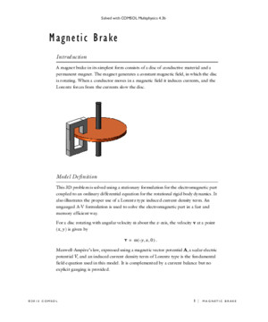
Solved with COMSOL Multiphysics 42 ©2011 COMSOL 1 | ELECTROMAGNETIC FORCES ON PARALLEL CURRENT-CARRYING WIRES Electromagnetic Forces on Parallel Current-Carrying Wires Introduction One ampere is defined as the constant current in two straight parallel conductors of infinite length and negligible circular cross section, placed one meter apart in vacuum, that produces a force of 2·10 7 newton per meter of length (N/m) This model shows a setup of two parallel wires in the spirit of this definition, but with the difference that the wires have finite cross sectionsFor wires with circular cross section carrying a uniform current density as in this example, the mutual magnetic force will be the same as for line currents This can be understood by the following arguments: Start from a situation where both wires are line currents ( I ) Each line current will be subject to a Lorentz force ( I × B ) where the magnetic flux density ( B ) is the one produced by the other wire Now, give one wire a finite radius It follows directly from circular symmetry and Maxwell-Ampère’s law that, outside this wire, the produced flux density is exactly the same as before so the force on the remaining line current is unaltered Further, the net force on the wire with the distributed current density must be of exactly the same magnitude (but with opposite direction) as the force on the line current so that force did not change either If the two wires exchange places, the forces must still be the same and it follows from symmetry that the force is independent of wire radius as long as the wire cross sections do not intersect The wires can even be cylindrical shells or any other shape with circular symmetry of the cross section that For an experimental setup, negligible cross section is required as resistive voltage drop along the wires and Hall effect may cause electrostatic forces that increase with wire radius but such effects are not included in this modelThe force between the wires is computed using two different methods: first automatically by integrating the stress tensor on the boundaries, then by integrating the volume (Lorentz) force density over the wire cross section The results converge to 2·10 7 N/m for the 1 ampere definition, as expected Solved with COMSOL Multiphysics 422 | ELECTROMAGNETIC FORCES ON PARALLEL CURRENT-CARRYING WIRES©2011 COMSOL Model Definition The model is built using the 2D Magnetic Fields interface The modeling plane is a cross section of the two wires and the surrounding air DOMAIN EQUATIONS The equation formulation assumes that the only nonzero component of the magnetic vector potential is A z This corresponds to all currents being perpendicular to the modeling plane The following equation is solved: where is the permeability of the medium and J z e is the externally applied current J z e is set so that the applied current in the wires equals 1 A, but with different signsSurrounding the air is an infinite element domain For details, see Infinite Elements in AC/DC Module User’s Guide Results and Discussion The expression for the surface stress reads where n 1 is the boundary normal pointing out from the conductor wire and T 2 the stress tensor of air The closed line integral of this expression around the circumference of either wire evaluates to 199·10 7 N/m The minus sign indicates that the force between the wires is repulsive The software automatically provides the coordinate components of the force on each wireThe volume force density is given by The surface integral of the x component of the volume force on the cross section of a wire gives the result 200·10 7 N/mBy refining the mesh and re-solving the problem, you can verify that the solution with both method converges to 2·10 7 (N/m) The volume force density integral will typically be the most accurate one for reasons explained in Calculating Accurate Fluxes in the COMSOL Multiphysics User’s Guide A z J z e = n 1 T 2 12 --- H B n 1 – n 1 H B T += F J B J z e – B y J z e B x 0 = = Solved with COMSOL Multiphysics 42 ©2011 COMSOL 3 | ELECTROMAGNETIC FORCES ON PARALLEL CURRENT-CARRYING WIRES Model Library path: ACDC_Module/Verification_Models/parallel_wires Modeling Instructions MODEL WIZARD 1 Go to the Model Wizard window 2 Click the 2D button 3 Click Next 4 In the Add physics tree, select AC/DC>Magnetic Fields (mf) 5 Click Next 6 In the Studies tree, select Preset Studies>Stationary 7 Click Finish GLOBAL DEFINITIONS Parameters 1 In the Model Builder window, right-click Global Definitions and choose Parameters 2 Go to the Settings window for Parameters 3 Locate the Parameters section In the Parameters table, enter the following settings: GEOMETRY 1 Circle 1 1 In the Model Builder window, right-click Model 1>Geometry 1 and choose Circle 2 Go to the Settings window for Circle 3 Locate the Size and Shape section In the Radius edit field, type 15 Circle 2 In the Model Builder window, right-click Geometry 1 and choose Circle NAME EXPRESSION DESCRIPTION r 02[m] Wire radiusI0 1[A] Total currentJ0 I0/(pi*r^2) Current density
Recommended