HW4
There is document - HW4 available here for reading and downloading. Use the download button below or simple online reader.
The file extension - PDF and ranks to the Documents category.

400
views
Tags
Related
Comments
Log in to leave a message!
Description
Download HW4
Transcripts
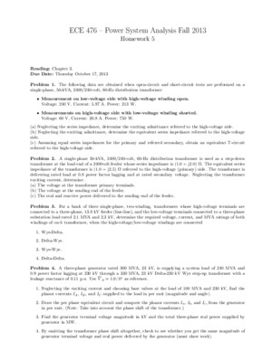
ECE 476 – Power System Analysis Fall 2013 Homework 4 Due Date: Tuesday October 1, 2013 Problem 1 A 500-km, 500-kV, 60-Hz uncompensated three-phase line has a positive-sequence series impedance z = 0 03 + j 0 35 Ω/km and a positive-sequence shunt admittance y = j 4 4 x 10 − 6 S/km Calculate:(a) Z c (b) ( γd )(c) The exact ABCD parameters for this line Problem 2 A 320-km 500-kV, 60-Hz three-phase uncompensated line has a positive-sequence series reactancex=034 Ω/km and a positive-sequence shunt admittance y=45 x 10 − 6 S/km Neglecting losses, calculate:(a) Its characteristic impedance Z c (b) The value of γd (c) The exact ABCD parameters for this line(d) The surge impedance loading in MW Problem 3 The per-phase impedance of a short three-phase transmission line is 0 5 53 15 ◦ Ω The three-phase load at the receiving end is 900 kW at 0 8 pf lagging If the line-to-line sending-end voltage is 3 3 kV,determine:(a) The receiving-end line-to-line voltage in kV(b) The line current(c) The phasor diagram with the line current I , as reference Problem 4 To maintain a safe “margin” of stability, system designers have decided that the power angle θ 12 := θ 1 − θ 2 , where θ 1 is the phase angle of the sending-end voltage and θ 2 is the phase angle of the receiving-end voltage, cannot be greater that 45 ◦ We wish to transmit 500 MW though a 300-mile line and need topick a transmission-line voltage level Consider 138 − , 345 − , and 765 − kV lines Which voltage level(s) wouldbe suitable? As a first approximation, assume that the voltage magnitudes on sending and receiving ends areequal, ie, V 1 = V 2 and the lines are loseless, ie, γ = jβ , with β = 0 002 rad/mi Problem 5 Given a transmission line described by a total series impedance Z = zd = 20 + j 80 Ω and a totalshunt admittance Y = yd = j 5 × 10 − 4 Ω(a) Find its characteristic impedance Z c , γd , e γd , sinh γd , and cosh γd (b) Suppose that the line is terminated in its characteristic impedance Z c Find the efficiency of the transmissionline in this case, ie, find η = − P 21 /P 12 , where P 21 is the active power flowing from the receiving end to thesending end of the line, and P 12 is the active power flowing from the sending end to the receiving end of theline1
Recommended


![[WIKI] 3M-54 Klub](imgdoc/99951.jpg)