gantry cranexls
There is document - gantry cranexls available here for reading and downloading. Use the download button below or simple online reader.
The file extension - PDF and ranks to the Documents category.

397
views
Tags
Related
Comments
Log in to leave a message!
Description
Download gantry cranexls
Transcripts
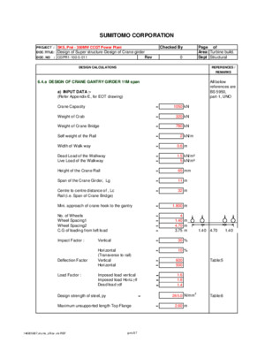
REF SUMITOMO CORPORATION PROJECT : SKS, Prai - 350MW CCGT Power Plant Checked By Page of DOCTITLE: Design of Super structure-Design of Crane-girder Area: Turbine build DOC NO : CGPR1-100-5-011 Rev 0 Dept Structural DESIGN CALCULATIONS REFERENCES / REMARKS 64a DESIGN OF CRANE GANTRY GIRDER 11M span All below references are a) INPUT DATA :- BS 5950, (Refer Appendix-E, for EOT drawing) part-1, UNO Crane Capacity = 1050 kN Weight of Crab = 320 kN Weight of Crane Bridge = 780 kN Self weight of the Rail = 2 kN/m Width of Walk way = 06 m Dead Load of the Walkway = 15 kN/m² Live Load of the Walkway = 5 kN/m² Height of the Crane Rail = 65 mm Span of the Crane Girder, Lg = 11 m Centre to centre distance of , Lc = 32 m Rail (ie Span of Crane Bridge) Mini approach of crane hook to the gantry = 1800 m No of Wheels = 4 Wheel Spacing1 = 140 m Wheel Spacing2 = 470 m CG of loading from left load = 375 m 140 470 140 Impact Factor : Vertical = 30 % Horizontal = 10 % (Transverse to rail) Deflection Factor Vertical = 600 Table:5 Horizontal = 500 Load Factor : Imposed load vertical -gIvf = 16 Imposed load HorizgIhf = 16 Dead load gdf = 14 Design strength of steel, py = 2650 N/mm2 Table:6 Maximum unsupported length Top Flange = 260 m Depth of the surge girder = 060 m Maximum unsupported length Bottom Flange = 260 m 180m (1050+320)kN 780 kN Kicker RL 3200m RR RL = (1370 x 3020 + 780 x 3200/2)/3200= 1682938 kN Wheel Load by calculation 42073 kN/wheel Wheel Load by Vendor = 42073 kN/wheel b) LOAD CALCULATIONS: b1) Vertical Loads b1a) Conc Loads Max static Wheel Load say Wm = 421 kN 8757 8757 Load due to Impact = 030 x 421 = 1263 kN Total load = 547 kN Factored Load Wmf = 160 x 54730 = 87568 kN 140 470 140 b1b) Uniform Dirstributed Load Self weight of rail = 200 kN/m Walkway Dead Load = 045 kN/m Walkway Live Load = 150 kN/m Self weight of girder = 466 kN/m 861 kN/m Factored load Wdf = 140 x 861 1206 kN/m b2) Horizontal Loads Maximum lateral load per wheel is equal to 10% Static vertical wheel load, l = 01 from Fig-1 Max Lateral load WH = 010(421*4) = 1684 kN BS:2573,part-1 4 wheels are resisting the total lateral load Factored lateral load Wdf = 160 x 16840 / 4 6736 kN/wheel c) MAXIMUM BENDING MOMENT AND SHEAR FORCE: c1) For vertical loads c1a) Bending Moment :- The maximum Bending moment under moving loads occurs when line of action of one load and centre of gravity of the loads are at equal distance from the centre of span 87568kN 87568kN 87568kN 87568kN 1206kN/m C RA RB 1100m Reactions :- Ra = 4x87568x(11 - 11*05 - 025*47)/11 = 1443525 kN + 1206 x 11 /2 Rb = 4x87568+1206x11- 1,443525 = 2191834 kN Maximum Bending moment occurs at C = Mux1 = (144353 x 433) -87568 x 14 - (1206 x 433²/2) = 4904517 kNm c1b) Shear Force:- 87568kN 87568kN 1206kN/m RA 1100m Reactions: RA = 4 x 8757 x [110-38] /11+ (121 x 110/2) 2374930 kN RB = (4 x 8757) + (121 x 110) - 237493 1260428 kN Max Reaction = 2374930 kN c2) For Horizontal loads :- 6736kN C c2a) Local Bending Moment at C, Crane Girder is laterally bending between Node points of surge Girder Muy = 67360 x 26 /4 43784 kNm c2b) Axial Force: Because of Lateral force, the Crane Girder is subjected to axial force Max lateral bending Moment 49045 x 6736 / 87568 37727 kN-m F=Axial force in the surge girder 37727 / 06 62878 kN c2c) Shear force :- 6736kN 6736kN RA 375m 1100m RB Reactions :- RA = 4x 674[110 - 38]1100 = 177585 kN RB = 4 x 67360 - 177585 = 91855 kN Max Horzontal reaction RH = 177585 kN d) DESIGN OF GANTRY GIRDER: y Depth 1250 mm Width 450 mm 20 t = 20 mm x x 1250 T = 40 mm 40 450 Properties :- Depth of the section, D = 1250 mm Width of the section, B = 450 mm Thickness of web, t = 20 mm Thickness of flange, T = 40 mm Effective depth of web, d = 1170 mm Second moment of inertia, Ixx = 159E+10 mm4 Second moment of inertia, Iyy = 608E+08 mm4 rmin = 10119 mm Section modulus, Zxx = 254E+07 mm3 Section modulus, Zyy = 270E+06 mm3 Plastic modulus, Sxx = 296E+07 mm3 Plastic modulus, Syy = 428E+06 mm3 Buckling parameter, u = 1 conservatively Torsional index, x : D/T = 3125 as per Cl4375 Sectional Area, A = 59400 mm2 Flange Area on one side, Ag = 18000 mm2 Out stand width of panel, b = 215 mm Constant, e, = sqrt(275/py) = 102 Outstand element of compression flange, b/T = 538 Plastic Cl352 and Web slenderness, d/t = 5850 Plastic Table:7 d1) Shear Capacity Web slenderness, d/t = 5850 < 63*102 Cl4441 Satisfactory Shear area parallel to the web, Avx=t*d = 23400 mm2 Cl423, Critical Shear strength, qcr for t/d =5850 = 159 N/mm2 Table:21, Shear Capacity, Vcr=qcr*Avx = 37206 kN Cl4453 >2,37493 kN Satisfactory d2) Moment capacity, Mb d2a) Lateral-torsional buckling moment, Mb: ( as per clause 4373 of BS 5950, part-1) Effective length factor = 100 Table:9 ( Destabilizing condition) (As per table:9,BS 5950,part-1: Beam partial restrained against rotation) Effective length, LE = 260 m Slenderness, l = LE/rmin = 2569 Equivalent slenderness, lLT = nunl Cl4375 Slenderness correction factor, n = 10 conservatively Uniform moment factor, m = 10 conservatively Buckling parameter, u = 1000 l/x = 0822 N = 050 Slenderness factor, n = 100 Table:14 lLT = 2569 pb = 26500 N/mm2 Table:12 Buckling resistance, Mb = pb*Sxx = 784323 kNm Satisfactory >490452 kNm Cl4372 > m*Mux1 e) CHECK FOR COMBINED BENDING COMPRESSIVE STRESS IN EXTREME FIBRE (FOR VERTICAL PLUS LATERAL) e1) Compressive strength pc :- Slenderness, l = LE/rmin = 2569 Reduced design strength, py = 24500 N/mm2 Cl475 pc = 24000 N/mm2 Table:27c e2) Overall buckling check (As per Clause 48331, BS 5950: part-1) F/Ag*pc + mMux1/Mb + mMuy/py*Zyy = 0832 Satisfactory < 1000 f) CHECK FOR LONGITUDINAL STRESS: Height of rail = 65 mm 5% of the static wheel load = 5/100 x4x 8757 17514 kN Bending moment in the longitudinal direction is equal to Longitudinal Force into Crane Rail Depth plus half of Crane Girder depth Mux2 = 175136 x (65 + 6250) 12084 kNm CHECK FOR COMBINED BENDING COMPRESSIVE STRESS IN EXTREME FIBRE (FOR VERTICAL PLUS LONGITUDINAL) F/Ag*pc + m(Mux1+Mux2)/Mb = 0681 Satisfactory g) CHECK FOR DEFLECTION: Allowable deflection for vertical loads d lim, v = Span / 600 =11,0000 / 6000 = 1833 mm Allowable deflection for horizontal loads d lim, h = Span / 500 = 11,0000 /500 = 2200 mm Vertical Deflection:- 315 175 5473kN 5473kN 861kN/m c RA 1100 RB d v = = ((5/384)(861 x 11000^4)/( 205000 x 159e+10))+ {( 2 x 547300 x 11000³)/( 48 x 205000 x 159E+10)} x {[3 x 175/11 - 4 x (175/11)³] + [3 x 315/11 - 4 x (315/11)³]} = 11960 mm CHECK dv < Allowable Deflection 11960 < 183 HENCE SAFE 0 h) Crane Girder Welding Calculation Top Flange & Web is welded by full Penetration Butt weld Bottom Flange Weld Horizontal Shear = FAy/ Ixx A- Area of the Bottom Flange = 18000 mm2 y - CG of flange Plate from CG of section = 605 mm Ixx of the section = 159E+10 mm4 Maximum vertical shear = 2374930 kN Horizontal Shear 2,3749 x 1000 x 18000x605 / 15851055000 1631626 N/mm Size of the weld on each side 1,6316/ ( 2 x 215x 0707) 5421 mm Provide weld as = 12 mm i) DESIGN OF BEARING STIFFENER Bearing check: Minimum area of stiffener in contact with the flange = 08*Fx/pys Cl4542 Fx = External reaction pys = Design strength of stiffener Minimum Area of stiffener required = 716960 mm2 Conside Thk Of Stiffener , ts = 2500 mm Width of the stiffener, bs = 45000 mm Area of the stiffener = 1125000 mm2 Satisfactory Check for outstands Outstand from the face of the web = bs/2-web thickness = 21500 mm Outstand of web stiffeners, as per Cl4512 of BS5950: Limits: 19tse = 48388 mm 13tse = 33108 mm Satisfactory Bearing resistance of the stiffener Bearing Stress in member = 21110 N/mm2 < 265 N/mm2 Satisfactory Buckling resistance of the stiffner (as per Cl4515 of BS5950,part-1) Design strength of the stiffner in buckling = py-20 Cl4515 = 2450 N/mm2 Buckling resistance check as a column: Area of combined section 450 x25 + 20 x 20 x 20 1925000 mm2 Ixx = 190E+08 mm4 = 9938 mm l = l / Rmin =1250x 1000 / 994 = 1258 Compressive strength, pc = 24500 N/mm2 Tb27c, Buckling resistance of the stiffener = 471625 kN > 237493 kN Satistactory Weld between Stiffener & web Vetical Height avilable for Welding = 117000 mm Thk of weld reqd =2,3749 x1000/(1170x2x07*215) 674 mm Provide weld thickness = 1200 mm j) Shear buckling of Web under Wheel load Web bearing under wheel load (as per Cl4114,BS 5950, part-1) Load dispersion under wheel,lw= 2(Height of the wheel + Thickness of the flange) = 210 mm Bearing Capacity = lw*py*t = 1113 kN > 87568 kN Satisfactory Web buckling under wheel load (as per Cl4521, BS 5950,part-1) b1 = Stiff bearing length = 2(Height of the crane rail) = 13000 mm n1 = Dispersion at 45degrees through half the depth of the section = (depth of the web + 2*thickness of the flange) = 1250 mm d = Depth of the web = 1170 mm Web slenderness, l = 25*depth of the web/thickness of the web Cl4521 = 14625 Compressive resistance, pc = 70 N/mm2 Table 27c Buckling resistance, Pw = (b1+n1)*t*pc = 193200 kN > 87568 kN Satisfactory k) Connection for Longitudinal Force Longitudinal Force = 17514 kN Dia of bolt provided = 2400 mm No of bolts provided = 400 Stress in Bolts = 9678 N/mm2 < 160 N/mm2 l) Design of Surge Girder Design of bracing members Maximum Horizontal force = 177585 kN Max Force in diagonal = 3351 kN Angles provided = 100X100X8 RSC Area of the Section = 1560 cm2 Rmin of the section = 307 cm Length of diagonal = 150 m Inclination of diagonal wrt Horizontal = 3200 Stress in member = 21482 N/mm2 (Nobays are not to count in the sketch) Allowable Stress in member l=15 *100 / 307 = 4886 Compressive stress, pc = 22500 N/mm2 Table 27c > 21482 Satisfactory Design of bottom chord member (as surge may come on either direction, bottom chord members are designed for compression) Member size provided = 300X150X32 MS profile Area of the Section = 4080 cm2 Rmin of the section = 329 cm Unsupported length = 260 m Maximum axial force, F = 62878 kN Stress in member = 15411 N/mm2 Allowable Stress in member l=26 *100 / 329 = 7903 Compressive stress, pc = 16100 N/mm2 Table 27c > 15411 Satisfactory j) Design of Crane Girder Bracket Depth of the bracket, Db = 1200 mm Width of the flange plate, Wb = 60000 mm Thickness of the flange plate, Tb = 3200 mm Thickness of the web plate, tb = 2500 mm Eccetricity of Crane girder from grid = 100 m Maximum Vertical force = 237493 kN Design for Moment Moment due to eccentricity, Me = 237493 kNm Axial Force in Top flange, Ab=Me/Db = 197911 kN Stress in top flange=Ab/Wb*Tb = 103078569405 N/mm2 < 2650 N/mm2 Satisfactory Design for shear Web slenderness = 4544 < 63*102 Cl4441 Satisfactory Shear area parallel to the web = 28400 mm2 Cl423, Critical Shear strength = 159 N/mm2 Cl423 Shear Capacity, = 45156 kN >2,37493 kN Satisfactory &L&7&F xls &A &6 &C&7gvrs/ST CG OF GANTRY CG OF LOADS = = CG OF LOADS Mid Span of Crane Girder = = CG OF GANTRY ISMC Name Depth Breadth wt/m Tf Tw Cyy G Ixx Iyy Rxx Ryy Zxx Zyy Area mm mm kN/m mm mm mm mm mm4 mm4 mm mm mm3 mm3 mm2 ISMC 75 75 40 00681 730 440 1310 21 760000 126000 2960 1210 20300 4700 867 ISMC 100 100 50 00918 750 470 1530 28 1867000 259000 4000 1490 37300 7500 1170 ISMC 125 125 65 01271 810 500 1940 35 4164000 599000 5070 1920 66600 13100 1619 ISMC 150 150 75 01639 900 540 2220 40 7794000 1023000 6110 2210 103900 19400 2088 ISMC 175 175 75 01914 1020 570 2200 40 12233000 1210000 7080 2230 139800 22800 2438 ISMC 200 200 75 02214 1140 610 2170 40 18193000 1404000 8030 2230 181900 26300 2821 ISMC 225 225 80 02591 1240 640 2300 45 26946000 1872000 9030 2380 239500 32800 3301 ISMC 250 250 80 03036 1410 710 2300 45 38168000 2191000 9940 2380 305300 38400 3867 ISMC 300 300 90 03583 1300 760 2360 50 63626000 3108000 11810 2610 424200 46800 4564 ISMC 350 350 100 04212 1350 810 2440 60 100080000 4306000 13660 2830 571900 57000 5366 ISMC 400 400 100 04940 1530 860 2420 60 150828000 5048000 15480 2830 754100 66600 6293 &R&D &T &L&F&CPage &P of &N&R&A ISMB Section H B wt/m A Tf Tw R1 R2 H1 H2 G Ixx Iyy Rxx Ryy Zxx Zyy mm mm kN/m mm2 mm mm mm mm mm mm mm mm4 mm4 mm mm mm3 mm3 ISMB100 100 75 0115 1460 72 40 90 45 650 1750 35 2575000 408000 420 167 51500 10880 ISMB125 125 75 0130 1660 76 44 90 45 892 1790 35 4490000 437000 520 162 71840 11653 ISMB150 150 80 0149 1900 76 48 90 45 1139 1805 40 7264000 526000 618 166 96853 13150 ISMB175 175 90 0193 2462 86 55 100 50 1345 2025 50 12720000 850000 719 186 145371 18889 ISMB200 200 100 0254 3233 108 57 110 55 1527 2365 55 22354000 1500000 832 215 223540 30000 ISMB225 225 110 0312 3972 118 65 120 60 1733 2585 60 34418000 2183000 931 234 305938 39691 ISMB250 250 125 0373 4755 125 69 130 65 1941 2795 65 51314000 3345000 1039 265 410512 53520 ISMB300 300 140 0442 5626 124 75 140 70 2416 2925 80 86034000 4539000 1237 284 573560 64843 ISMB350 350 140 0524 6671 142 81 140 70 2880 3100 80 136303000 5377000 1429 284 778874 76814 ISMB400 400 140 0616 7846 160 89 140 70 3344 3280 80 204584000 6221000 1615 282 1022920 88871 ISMB450 450 150 0724 9227 174 94 150 75 3792 3540 90 303908000 8340000 1815 301 1350702 111200 ISMB500 500 180 0869 11074 172 102 170 85 4241 3795 100 452183000 13698000 2021 352 1808732 152200 ISMB600 600 210 1226 15621 208 120 200 100 5097 4515 140 918130000 26510000 2424 412 3060433 252476 &R&D &T &L&F&CPage &P of &N&R&A CRANE DESIGN OF CRANE GANTRY GIRDER Project : PRAI POWER 350 MW CCGT POWER PLANT PROJECT Building : CW PUMPHOUSE ( INTERNAL) Girder Type : EXISTING CRANE BEAM - DESIGN CHECK 1) INPUT DATA (Refer Appendix-A, for EOT drawing) All below references are Crane Capacity = 100 kN BS 5950, part-1, Weight of Crab = 0 kN Weight of Crane Bridge = 0 kN Self weight of the Rail = 1 kN/m Height of the Crane Rail = 70 mm Span of the Crane Girder, Lg = 87 m Centre to centre distance of , Lc = 1000000 m Rail (ie Span of Crane Bridge) Mini approach of crane hook to the gantry = 1000 m No of Wheels = 2 Wheel Spacing1 = 060 m CG of loading from left load = 030 m Impact Factor : Vertical = 30 % Horizontal = 10 % (Transverse to rail) On Stopper = 16 kN Deflection Factor Vertical = 1000 Table:5 Horizontal = 1000 Load Factor : Imposed load vertical -gIvf = 16 Imposed load HorizgIhf = 16 Dead load gdf = 14 Design strength of steel, py = 275 N/mm2 Table:6 Maximum unsupported length Top Flange = 870 m Maximum unsupported length Bottom Flange = 870 m 2) LOAD CALCULATIONS Wheel load calculation RL = (100 x 99999900 + 0 x 100000000/2)/100000000 = 100000 kN Max wheel Load by calculation = 5000 kN/wheel Wheel Load by Vendor = 5000 kN/wheel 2a) Vertical Loads i) Conc Loads Average static Wheel Load say Wm = 500 kN 1040 1040 Load due to Impact = 030 x 50 = 1500 kN Total load = 65 kN Factored Load Wmf = 160 x 6500 = 10400 kN 060 000 060 ii) Uniform Dirstributed Load Self weight of rail = 100 kN/m Self weight of girder = 149 kN/m 249 kN/m Factored load Wdf = 140 x 249 = 349 kN/m 2b) Horizontal Loads Maximum lateral load per wheel is equal to 10% Static vertical wheel load, l = 01 from Fig-1 Max Lateral load WH = 010(50*2) = 100 kN BS:2573,part-1 2 wheels are resisting the total lateral load Factored lateral load Wdf = 160 x 1000 / 2 = 800 kN/wheel 2c) Stopper Loads Factored lateral load Wsp = 160 x 1600 = 256 kN/stopper 3) MAXIMUM BENDING MOMENT AND SHEAR FORCE 3a) For vertical loads i) Bending Moment The maximum Bending moment under moving loads occurs when line of action of one load and centre of gravity of the loads are at equal distance from the centre of span ( refer diagram at deflection check) Reactions :- Ra = 104x(1 + 060/2/87) +349x870/2 = 12276 kN Rb = 2x10⁴+349x87- 122759 = 11559 kN Maximum Bending Moment Mux1 = (12276 x 435) -104 x 045 - (349 x 435²/2) = 35520 kNm ii) Shear Force:- Reactions: RA = 2 x 1040 x [87-03] /87+ (35 x 87/2) = 21600 kN RB = (2 x 1040) + (35 x 87) - 21600 = 2235 kN Max Reaction = 21600 kN 3b) For Horizontal loads i) Local Bending Moment at C, Crane Girder is laterally bending between points of restrained at support Muy = 8000 x 87 /4 = 1740 kNm ii) Shear force Reactions :- RA = 2x 80[87 - 03]870 = 15448 kN RB = 2 x 8000 - 15448 = 0552 kN Max Horzontal reaction RH = 15448 kN 4) DESIGN OF GANTRY BEAM Properties :- Depth of the section, D = 6099 mm UB610X305X149kg/m Width of the section, B = 3048 mm Thickness of web, t = 119 mm Thickness of flange, T = 197 mm Effective depth of web, d = 5372 mm Second moment of inertia, Ixx = 125E+09 mm4 Second moment of inertia, Iyy = 930E+07 mm4 rmin = 6990 mm Section modulus, Zxx = 409E+06 mm3 Section modulus, Zyy = 610E+05 mm3 Plastic modulus, Sxx = 457E+06 mm3 Plastic modulus, Syy = 937E+05 mm3 Buckling parameter, u = 0886 Torsional index, x : D/T = 325 Sectional Area, A = 19000 mm2 Flange Area on one side, Ag = 6005 mm2 Out stand width of panel, b = 14645 mm Constant, e, = sqrt(275/py) = 100 Outstand element of compression flange, b/T = 743 Plastic Cl352 and Web slenderness, d/t = 4514 Plastic Table:7 4a) Shear Capacity Web slenderness, d/t = 4514 < 63*100 Cl4441 Satisfactory Shear area parallel to the web, Avx=t*d = 639268 mm2 Cl423, Critical Shear strength, qcr for d/t =4514 = 165 N/mm2 Table:21, Shear Capacity, Vcr=qcr*Avx = 105479 kN Cl4453 > 216 kN Satisfactory 4b) Moment capacity, Mb i) Lateral-torsional buckling moment, Mb: ( as per clause 4373 of BS 5950, part-1) Effective length factor = 120 Table:9 ( Destabilizing condition) (As per table:9,BS 5950,part-1: Beam partial restrained against rotation) Effective length, LE = 1044 m Slenderness, l = LE/rmin = 14936 Equivalent slenderness, lLT = nunl Cl4375 Slenderness correction factor, n = 10 conservatively Uniform moment factor, m = 10 conservatively Buckling parameter, u = 0886 l/x = 4596 N = 050 Slenderness factor, n = 082 Table:14 lLT = 10851 pb = 10900 N/mm2 Table:11 Buckling resistance, Mb = pb*Sxx = 49813 kNm Satisfactory >35520 kNm Cl4372 > m*Mux1 5) CHECK FOR COMBINED BENDING COMPRESSIVE STRESS IN EXTREME FIBRE (FOR VERTICAL PLUS LATERAL) 5a) Compressive strength pc Slenderness, l = LE/rmin = 14936 pc = 81 N/mm2 Table 27c 5b) Overall buckling check (As per Clause 48331, BS 5950: part-1) mMux1/Mb + mMuy/py*Zyy = 0817 Satisfactory < 1000 6) CHECK FOR LONGITUDINAL STRESS Height of rail = 70 mm 5% of the static wheel load = 5/100 x2x 1040 1040 kN Bending moment in the longitudinal direction is equal to Longitudinal Force into Crane Rail Depth plus half of Crane Girder depth Mux2 = 10400 x (70 + 3050) = 390 kNm CHECK FOR COMBINED BENDING COMPRESSIVE STRESS IN EXTREME FIBRE (FOR VERTICAL PLUS LONGITUDINAL) F/Ag*pc + m(Mux1+Mux2)/Mb = 0742 Satisfactory 7) CHECK FOR DEFLECTION Allowable deflection for vertical loads d lim, v = Span / 1000 =8,7000 / 1,0000 = 870 mm Allowable deflection for horizontal loads d lim, h = Span / 1000 = 8,7000 /1,000 = 870 mm Vertical Deflection:- 45 42 390 65kN 65kN 249kN/m c RA 870 RB d v = d v = ((5/384)(249 x 8700^4)/( 205000 x 125e+09))+ {( 65000 x 8700³)/( 48 x 205000 x 125E+09)} x {[3 x 390/9 - 4 x (390/9)³] + [3 x 420/9 - 4 x (420/9)³]} = 7625 mm CHECK dv < Allowable Deflection 7625 < 87 HENCE SAFE 0 8) SHEAR BUCKING OF WEB UNDER WHEEL LOAD 8a) Web bearing under wheel load (as per Cl4114,BS 5950, part-1) Load dispersion under wheel,lw= 2(Height of the wheel + Thickness of the flange) = 1794 mm Bearing Capacity = lw*py*t = 5870865 kN > 10400 kN Satisfactory 8b) Web buckling under wheel load (as per Cl4521, BS 5950,part-1) b1 = Stiff bearing length = 2(Height of the crane rail) = 14000 mm n1 = Dispersion at 45degrees through half the depth of the section = (depth of the web + 2*thickness of the flange) = 6099 mm d = Depth of the web = 5705 mm Web slenderness, l = 25*depth of the web/thickness of the web Cl4521 = 11985 Compressive resistance, pc = 97 N/mm2 Table 27c Buckling resistance, Pw = (b1+n1)*t*pc= 86561 kN = > 10400 kN Satisfactory 9) CONNECTION FOR LONGITUDINAL LOAD Longitudinal Force = 1040 kN Dia of bolt provided = 16 mm No of bolts provided = 2 Stress in Bolts = 2586 N/mm2 < 160 N/mm2 10) DESIGN OF STOPPER BRACKET Depth of the bracket, Dsp = 250 mm Width of the bracket, Wsp = 102 mm Thickness of the bracket plate, Tsp = 6 mm Thickness of stiffener plate, Ts = 6 mm No of stiffener plate, Ns = 1 nos Distance between Stopper and flange of Crane girder = 020 m Maximum Stopper force = 160 kN Maximum ultimate Stopper force, S = 256 kN 10a) Design for Moment Moment due to eccentricity, Mc = 512 kNm Combined plate CG, x = 912 mm Combined plate Ixx = 140E+07 mm4 Distance of compression edge = 1588 mm Combined plate Zxx = 88189 mm3 Moment capacity, Mc = PypZxx = 2425 kNm Cl41324 > 512 kNm Satisfactory 10b) Weld between Bracket and flange of Crane Girder Design strength of fillet weld, pw = 215 N/mm2 Tb36, BS5950 Weld thickness = 6 mm Effective length of flange weld = 400 mm Maxbending tension in bracket, T = M/x = 562 kN Capacity of bracket weld under tension = 3612 kN > 562 kN Satisfactory OK 10c) Weld between Stiffener and flange of Crane Girder Weld thickness = 6 mm Effective length of flange weld, 2Hs = 488 mm Max shear force per stiffner, S/Ns = 2560 kN Capacity of flange weld under tension = 9030 kN > 256 kN Satisfactory OK CG OF GANTRY CG OF LOADS = = MBD000A26F6unknown MBD00032958unknown MBD0007C2C7unknown
Recommended