Estimating MOSFET Parameters from the Data Sheet.pdf
There is document - Estimating MOSFET Parameters from the Data Sheet.pdf available here for reading and downloading. Use the download button below or simple online reader.
The file extension - PDF and ranks to the Documents category.
Tags
Related
Comments
Log in to leave a message!
Description
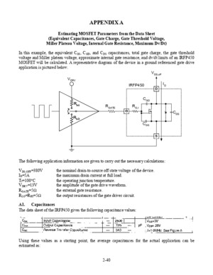
2-40 APPENDIX A Estimating MOSFET Parameters from the Data Sheet (Equivalent Capacitances, Gate Charge, Gate Threshold Voltage, Miller Plateau Voltage, Internal Gate Resistance, Maximum Dv/Dt) In this example, the equivalent C GS , C GD , and C DS capacitances, total gate charge, the gate threshold voltage and Miller plateau voltage, approximate internal gate resistance, and dv/dt limits of an IRFP450 MOSFET will be calculated A representative diagram of the device in
Transcripts
2-40 APPENDIX A Estimating MOSFET Parameters from the Data Sheet(Equivalent Capacitances, Gate Charge, Gate Threshold Voltage,Miller Plateau Voltage, Internal Gate Resistance, Maximum Dv/Dt) In this example, the equivalent C GS , C GD , and C DS capacitances, total gate charge, the gate thresholdvoltage and Miller plateau voltage, approximate internal gate resistance, and dv/dt limits of an IRFP450MOSFET will be calculated A representative diagram of the device in a ground referenced gate driveapplication is pictured below V DRV DSG R HI R GATE R G,I C GD C GS C DS R LO IRFP450 I D V DS,off The following application information are given to carry out the necessary calculations:V DS,OFF =380Vthe nominal drain-to-source off state voltage of the deviceI D =5Athe maximum drain current at full loadT J =100 ° Cthe operating junction temperatureV DRV =13Vthe amplitude of the gate drive waveformR GATE =5 Ω the external gate resistanceR LO =R HI =5 Ω the output resistances of the gate driver circuit A1Capacitances The data sheet of the IRFP450 gives the following capacitance values:Using these values as a starting point, the average capacitances for the actual application can beestimated as: 2-41Equations:Numerical Example: off DS,specDS,specOSS,aveOSS, off DS,specDS,specRSS,aveRSS, VVC2CVVC2C ⋅⋅=⋅⋅= 369pF380V25V720pF2C174pF380V25V340pF2C aveOSS,aveRSS, =⋅⋅= =⋅⋅= The physical capacitor values can be obtained from the basic relationships: aveRSS,aveOSS,DS RSSISSGSaveRSS,GD CCCCCCCC −=−== 195pF174pF369pFC 2260pF340pF2600pFC 174pFC DSGSGD =−==−== Notice that C GS is calculated from the srcinal data sheet values Within one equation, it is important touse capacitor values which are measured under the same test conditions Also keep in mind that C GS isconstant, it is not voltage dependent On the other hand, C GD and C DS capacitors are strongly non-linear and voltage dependent Their highest value is at or near 0V and rapidly decreasing as the voltageincreases across the gate-to-drain and drain-to-source terminals respectively A2Gate charge The worst case gate charge numbers for a particular gate drive amplitude, drain current level, and drainoff state voltage are given in the IRFP450 data sheetCorrecting for a different gate drive amplitude issimple using the typical Total Gate Charge curve asillustrated on the leftStarting from the 13V gate-to-source voltage on theleft hand side, find the corresponding drain-to-source voltage curve (interpolate if not givenexactly), then read the total gate charge value on thehorizontal axesIf a more accurate value is required, the differentgate charge components must be determinedindividually The gate-to-source charge can beestimated from the curve on the left, only the correctMiller plateau level must be known The Miller charge can be calculated from the C RSS,AVE valueobtained in A1 Finally, the over drive chargecomponent – raising the gate-to-source voltage fromthe Miller plateau to the final amplitude – should beestimated from the graph on the left again 13V122nC 2-42 A3Gate threshold and Miller plateau voltages As it was already shown in A2, and will be demonstrated later, several MOSFET switchingcharacteristic are influenced by the actual value of the gate threshold and Miller plateau voltages Inorder to calculate the Miller plateau voltage, one possibility would be to use the gate-to-source thresholdvoltage (V TH ) and transconductance (g fs ) of the MOSFET as listed in the data sheetUnfortunately, the threshold is not very well defined and the listed g fs is a small signal quantity A moreaccurate method to obtain the actual V TH and Miller plateau voltages is to use the Typical Transfer Characteristics curves of the data sheetFrom the same temperature curve, pick two easy toread points and note the corresponding draincurrents and gate-to-source voltages Select thedrain current values to correspond to vertical gridlines of the graph, that way the currents can be readaccurately Then follow the intersections to thehorizontal axes and read the gate-to-source voltagesStarting with the drain currents will result in higher accuracy because the gate-to-source voltage is on alinear scale as opposed to the logarithmic scale indrain current It is easier to estimate Vgs1 and Vgs2on the linear scale therefore the potential errors aremuch smallerFor this example, using the 150 ° C curve:567VV20AI413VV3AI GS2D2GS1D1 ==== The gate threshold and Miller Plateau voltages can be calculated as: ( )( )( ) K IVVVVIK IIIVIV VVVK I VVK I LOADTHMiller GS,2THGS1D1D1D2D1GS2D2GS1 TH2THGS2D22THGS1D1 +=−=−⋅−⋅=−⋅=−⋅= ( ) 4413V31695A3157VV31693157V413V3AK 3157V3A20A3A567V20A413V V Miller GS,2TH =+==−==−⋅−⋅= I D1 I D2 V GS1 V GS2 Typical Transfer Characteristics
Recommended

