Ccnpv7 Route Lab1-1 Ripng Student
There is document - Ccnpv7 Route Lab1-1 Ripng Student available here for reading and downloading. Use the download button below or simple online reader.
The file extension - PDF and ranks to the Documents category.

383
views
Tags
Related
Comments
Log in to leave a message!
Description
Download Ccnpv7 Route Lab1-1 Ripng Student
Transcripts
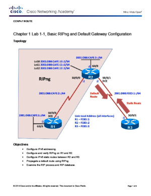
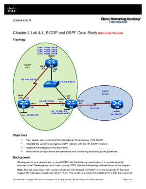
© 2014 Cisco and/or its affiliates All rights reserved This document is Cisco Public Page 1 of 9 CCNPv7 ROUTE Chapter 1 Lab 1-1, Basic RIPng and Default Gateway Configuration Topology Objectives Configure IPv6 addressing Configure and verify RIPng on R1 and R2 Configure IPv6 static routes between R2 and R3 Propagate a default route using RIPng Examine the RIP process and RIP database CCNPv7 ROUTE Lab 1-1, Basic RIPng and Default Gateway Configuration © 2014 Cisco and/or its affiliates All rights reserved This document is Cisco Public Page 2 of 9 Background In this lab you will be configuring a new network to connect a company’s Engineering, Marketing, and Accounting departments using IPv6 and RIPng on two routers You will also be configuring IPv6 static routing between the company’s gateway router (R2) and an ISP (R3) The gateway router will propagate the IPv6 default route via RIPng Your task is to configure RIPng to enable full connectivity between all routers Note: This lab uses Cisco 1941 routers with Cisco IOS Release 154 with IP Base The switches are Cisco WS-C2960-24TT-L with Fast Ethernet interfaces, therefore the router will use routing metrics associated with a 100 Mb/s interface Depending on the router or switch model and Cisco IOS Software version, the commands available and output produced might vary from what is shown in this lab Required Resources 3 routers (Cisco IOS Release 152 or comparable) 2 switches (LAN interfaces) Serial and Ethernet cables Step 0: Suggested starting configurations a Apply the following configuration to each router along with the appropriate hostname The exec-timeout 0 0 command should only be used in a lab environment Router(config)# no ip domain-lookup Router(config)# line con 0 Router(config-line)# logging synchronous Router(config-line)# exec-timeout 0 0 Step 1: Configure addressing and loopbacks b Using the addressing scheme in the diagram, apply IPv6 addresses to the Fast Ethernet interfaces and serial interfaces R1, R2, and R3 Then create Loopback1 on R1, Loopback2 on R2, and Loopback3 on R3 and address them according to the diagram R1(config)# interface GigabitEthernet 0/0 R1(config-if)# description Engineering Department R1(config-if)# ipv6 address 2001:db8:cafe:1::1/64 R1(config-if)# ipv6 address fe80::1 link-local R1(config-if)# no shutdown R1(config-if)# exit R1(config)# interface serial 0/0/0 R1(config-if)# description Serial link to R2 R1(config-if)# ipv6 address 2001:db8:cafe:2::1/64 R1(config-if)# ipv6 address fe80::1 link-local R1(config-if)# clock rate 64000 R1(config-if)# no shutdown R2(config)# interface GigabitEthernet 0/0 R2(config-if)# description Accounting Department R2(config-if)# ipv6 address 2001:db8:cafe:3::1/64 R2(config-if)# ipv6 address fe80::2 link-local R2(config-if)# no shutdown R2(config-if)# exit R2(config)# interface Loopback 10 R2(config-if)# description Marketing Department R2(config-if)# ipv6 address 2001:db8:cafe:10::1/64 CCNPv7 ROUTE Lab 1-1, Basic RIPng and Default Gateway Configuration © 2014 Cisco and/or its affiliates All rights reserved This document is Cisco Public Page 3 of 9 R2(config-if)# ipv6 address fe80::2 link-local R2(config-if)# exit R2(config)# interface Loopback 11 R2(config-if)# description Marketing Department R2(config-if)# ipv6 address 2001:db8:cafe:11::1/64 R2(config-if)# ipv6 address fe80::2 link-local R2(config-if)# exit R2(config)# interface Loopback 12 R2(config-if)# description Marketing Department R2(config-if)# ipv6 address 2001:db8:cafe:12::1/64 R2(config-if)# ipv6 address fe80::2 link-local R2(config-if)# exit R2(config)# interface Serial 0/0/0 R2(config-if)# description Serial link to R1 R2(config-if)# ipv6 address 2001:db8:cafe:2::2/64 R2(config-if)# ipv6 address fe80::2 link-local R2(config-if)# no shutdown R2(config-if)# exit R2(config)# interface Serial 0/0/1 R2(config-if)# description Serial link to R3 R2(config-if)# ipv6 address 2001:db8:feed:1::2/64 R2(config-if)# ipv6 address fe80::2 link-local R2(config-if)# clock rate 64000 R2(config-if)# no shutdown R2(config-if)# exit R3(config)# interface Serial 0/0/1 R3(config-if)# description Serial link to R2 R3(config-if)# ipv6 address 2001:db8:feed:1::1/64 R3(config-if)# ipv6 address fe80::3 link-local R3(config-if)# no shutdown Leave the switch in its default (blank) configuration By default, all switch ports are in VLAN1 and are not administratively down Note: If the switch has been previously configured, erase the startup config, delete the vlandat file from flash memory, and reload the switch c Verify that the line protocol of each interface is up and that you can successfully ping across each link You should see output similar to the following on each router R2# show ipv6 interface brief GigabitEthernet0/0 [up/up] FE80::2 2001:DB8:CAFE:3::1 Serial0/0/0 [up/up] FE80::2 2001:DB8:CAFE:2::2 Serial0/0/1 [up/up] FE80::2 2001:DB8:FEED:1::2 Loopback10 [up/up] FE80::2 2001:DB8:CAFE:10::1 Loopback11 [up/up] FE80::2 2001:DB8:CAFE:11::1 Loopback12 [up/up] FE80::2
Recommended