A Broadband Dual-Mode Monopole Antenna Using
There is document - A Broadband Dual-Mode Monopole Antenna Using available here for reading and downloading. Use the download button below or simple online reader.
The file extension - PDF and ranks to the Documents category.

254
views
Tags
Related
Comments
Log in to leave a message!
Description
258 IEEE ANTENNAS AND WIRELESS PROPAGATION LETTERS, VOL 8, 2009 A Broadband Dual-Mode Monopole Antenna Using NRI-TL Metamaterial Loading Marco A Antoniades, Member, IEEE, and George V Eleftheriades, Fellow, IEEE Abstract—A printed monopole antenna is proposed which uses negative-refractive-index transmission-line (NRI-TL) metamaterial loading in order to achieve a broadband dual-mode operation The metamaterial-loaded monopole supports a predominately even-mode current at 55 GHz, which all
Transcripts
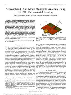
258 IEEE ANTENNAS AND WIRELESS PROPAGATION LETTERS, VOL 8, 2009 A Broadband Dual-Mode Monopole Antenna UsingNRI-TL Metamaterial Loading Marco A Antoniades , Member, IEEE , and George V Eleftheriades , Fellow, IEEE Abstract— A printed monopole antenna is proposed which usesnegative-refractive-index transmission-line (NRI-TL) metamate-rial loading in order to achieve a broadband dual-mode operationThe metamaterial-loaded monopole supports a predominatelyeven-mode current at 55 GHz, which allows the antenna tobe modeled as a short folded monopole Around 355 GHz, themetamaterial-loaded monopole acts as a balun for the groundplane currents, therefore rendering the entire top edge of theground plane as the main radiating element This in turn radiatesa dipolar mode that is orthogonal to the folded-monopole mode at55 GHz By virtue of the orthogonality between the two radiatingmodes, the metamaterial antenna exhibits a return-loss character-istic with a dual resonance, and therefore a very wide measuredimpedance bandwidth of 406 GHz The total size of the antennais only 22 30 mm, and the measured efficiency is on the orderof 90% at both 355 and 55 GHz Index Terms— Folded monopole antenna, metamaterials, nega-tive refractive index I I NTRODUCTION T HE recent inception of negative-refractive-index trans-mission-line (NRI-TL) metamaterials (MTM) [1], hasenabled the development of numerous new antenna designsthat take advantage of the unique characteristics that metama-terials have to offer Notable among these are a compact andmulti-band patch antenna [2], a low-profile 0 ring antennawith vertical polarization [3], a meandered dipole with a po-larization that is orthogonal to its length [4], a dual-band ringantenna with a linear or circular polarization [5] and an infinitewavelength antenna with monopolar radiation patterns [6]In this work, a printed monopole antenna that employsNRI-TL metamaterial loading is presented, that forms a naturalextension of the work carried out by the same authors in [3],[7], [8] and [9] for various electrically small MTM antennasThe different versions of the aforementioned MTM antennasconsisted of microstrip MTM unit cells arranged in a ringconfiguration over a truncated horizontal ground plane Eachof the MTM unit cells was designed to incur a 0 phase shiftat the design frequency, thus ensuring that the currents on eachof the vertical vias within the unit cells were in phase Thistechnique allows each of the MTM antennas to be modeled as ManuscriptreceivedDecember14,2008;revisedJanuary21,2009Firstpub-lished February 02, 2009; current version published May 06, 2009 This work was supported by the Natural Sciences and Engineering Research Council of Canada and Intel CorporationM A Antoniades and G V Eleftheriades are with the Edward S Rogers SrDepartment of Electrical and Computer Engineering, University of Toronto,Toronto, ON M5S 3G4, Canada (e-mail: mantoniawavesutorontoca;gelefthwavesutorontoca)Color versions of one or more of the figures in this letter are available onlineat http://ieeexploreieeeorgDigital Object Identifier 101109/LAWP20092014402Fig 1 NRI-TL metamaterial monopole antenna All dimensions are in mil-limeters: L =6 , W =5 , L =15 , W =30 , h =1 , L =4 , W =5 , L =3 : 45 , W =0 : 1 , h =1 : 59 , S =0 : 2 , W =1 : 55 , via diam-eter =0 : 5 a short multi-arm folded monopole that can be easily matchedto 50 without the use of an external matching network orbalun, and which radiates a vertical linear electric field [9]The antenna proposed herein and shown in Fig 1 also employsMTM loading in order to implement the folded monopole tech-nique within the widely popular printed monopole structure Asingle MTM unit cell is integrated directly onto the monopoleitself, which transforms the antenna into a folded monopolearound the frequency of 55 GHz, while at 355 GHz the MTMloading enables the ground plane of the antenna to radiate anorthogonal polarization Thus, the MTM-loaded monopoleantenna achieves a very wideband dual-resonance responsein a compact and low-profile design that does not require theuse of any chip lumped-element components Moreover, theantenna exhibits orthogonal polarizations in the 33–38 GHzWiMax and 515–585 GHz WiFi bands of interest, making itwell suited for use in low-cost multiple-input–multiple-output(MIMO) systems for wireless local area networks (WLAN)II A NTENNA D ESIGN The antennas considered in this work were designed on anFR4 substrate with parameters mm,and As a reference comparison, an unloadedCPW-fed printed monopole antenna with a total lengthof mm was first designed and simulated in Ansoft HFSSThisantennahadthesamedimensionsastheoneshowninFig1but without the MTM loading on the bottom side of the sub-strateThesimulatedreturn-losscharacteristicsfortheunloadedmonopole are shown in Fig 2 It exhibits a matched resonancearound 63 GHz with a return-loss bandwidth below dB of 236 GHz, from 531 to 767 GHzSince the performance of the unloaded monopole was abovetherangeofinterestforexistingWLANapplications,adifferent 1536-1225/2500 © 2009 IEEE Authorized licensed use limited to: LUNGHWA UNIV OF SCIENCE AND TECHNOLOGY Downloaded on October 25, 2009 at 09:02 from IEEE Xplore Restrictions apply ANTONIADES AND ELEFTHERIADES: BROADBAND DUAL-MODE MONOPOLE ANTENNA 259 Fig 2 Simulated return-loss characteristics of the unloaded and MTM-loadedprinted monopole antennas from Ansoft HFSSFig 3 NRI-TL metamaterial unit cell approach using metamaterial loading was pursued in order tomeet the WLAN specifications Capitalizing on the reducedsize that a MTM folded monopole has to offer [9], the printedmonopole was loaded on the bottom side of the substrate ina left-handed fashion as shown in Fig 1 This type of loadingwas inspired by the NRI-TL metamaterial unit cell shown inFig 3, and enables the MTM-loaded monopole to maintain itssmall form-factor while decreasing its operating frequency andextending its bandwidth Other monopole loading techniqueshave also been reported in the literature, for example in [10] aprinted monopole was loaded with an H-shaped conductor tocreate a band notch in the response of a UWB antennaIn the MTM-loaded monopole of Fig 1 the loading was car-ried out in an asymmetric fashion, where the series capacitancewasformedbetweenthemonopoleonthetopofthesubstrateand the rectangular patch on the bottom of the substrate, theshunt inductance was formed at the base of the monopole,whiletheshuntinductance wasformedbythethininductivestrip and via that join the bottom rectangular patch to the CPWground plane The length of the monopole itself and the bottompatch and thin inductive strip form the TL sections in Fig 3,with approximate parameters of andat 55 GHz The capacitance was adjusted by changing thelength of the bottom patch and the inductance was ad- justed by changing the width of the thin inductive strip inordertoobtainin-phasecurrentsalongthetopmonopolesectionand along the thin bottom strip at 55 GHz, thus forming a com-pact folded monopole The final dimensions of the optimizedMTM monopole antenna are outlined in Fig 1 Using these di-mensions, the extracted values for the loading elements were inthe range of 02 nH for , 3 nH for , and 05 pF for ,which when inserted into [9, eq (1)] result in a phase shift closeto 0 Fig 4 Surface current distributions on the conductors of the MTM-loadedmonopole antenna (a) 55 GHz (b) 355 GHz Thesimulatedreturn-losscharacteristicsfortheunloadedandthe MTM-loaded monopole antennas are both shown in Fig 2It can be observed that while the unloaded monopole exhibits asingle resonance around 63 GHz, the MTM-loaded monopoleexhibits a broadband dual-resonance, comprising the desiredresonance around 55 GHz together with an additional reso-nance around 355 GHz The MTM antenna has a simulatedreturn-loss bandwidth below dB of 384 GHz, from 315to 699 GHz Thus, it can be observed that the addition of theMTM loading to the short monopole not only reduces the oper-atingfrequencyfrom63to55GHz,butalsointroducesanotherresonancearound355GHz,whichislocatedatthecenterofthe33–38GHzWiMaxbandTheresonancearound355GHzcanbe tuned by changing the width of the ground plane , whilethe length of the ground plane can be used to change theinput impedance level A Principle of Operation The dual-mode operation of the antenna can be explained byconsideringthecurrentdistributionontheMTM-loadedantennaat each of the resonant frequencies, as shown in Fig 4 Thesefigures were sketched from the surface current distributions ob-served in Ansoft HFSS At 55 GHz, the MTM loading wasadjusted such that the current along the monopole and alongthe bottom thin inductive strip were in phase Thus, at this fre-quency the MTM loading was used to create a two-arm foldedmonopole, similar to the four-arm folded monopole of [9] Aswas outlined in [9], by adjusting the value of the loading in-ductance it is possible to effectively eliminate the odd-modecurrent on the monopole, enabling the even-mode current alongthe -direction to radiate, as shown in Fig 4(a) Additionally, at55 GHz, the currents along the top edges of the two groundplanes are out of phase and the balanced CPW mode is pre-served, therefore these currents do not contribute to any radi-ationAt355GHz,theantennanolongeractsasafoldedmonopolealongthe -axis,butratherasadipoleorientedalongthe -axisThis is a result of the in-phase currents along the top edges of both the ground plane sections as shown in Fig 4(b), whichrenderthegroundplaneasthemainradiatingelementatthisfre-quency This current distribution can be explained with the aidof the circuit diagram of Fig 3 At low frequencies the host TLsections can be considered negligible Assuming that the feedis placed at the base of the shunt inductor , the entire cir-cuit is simply transformed into a series resonator formed be-tween the loading capacitance and the loading inductance Authorized licensed use limited to: LUNGHWA UNIV OF SCIENCE AND TECHNOLOGY Downloaded on October 25, 2009 at 09:02 from IEEE Xplore Restrictions apply 260 IEEE ANTENNAS AND WIRELESS PROPAGATION LETTERS, VOL 8, 2009 Fig 5 Measured and simulated return-loss characteristics of the unloadedmonopole antenna, shown in the inset photograph Around 355 GHz the series resonator, which rep-resents the MTM-loaded monopole, forms a short circuit andtherefore acts as a balun for the currents on the ground planeThe phase of the current flowing on the right ground plane istherefore reversed, and is aligned with the current on the leftground plane This in turn enables the entire top edge of theground plane to radiate in a dipolar fashion As a consequence,the MTM-loaded monopole cannot be integrated onto a largerground plane and must be used as a stand-alone unit in order topreserve the radiating mode at 355 GHz As will be shown inthe next section, the dual-radiating nature of the antenna at 355and 55 GHz will also be verified by the orthogonal polariza-tions radiated at each of the aforementioned frequenciesIII S IMULATION AND E XPERIMENTAL R ESULTS Both the unloaded and the MTM-loaded monopole antennaswere fabricated and tested, and their photographs and return-loss characteristics are shown in Figs 5 and 6 In both casesthe simulated and measured responses match quite well, withthe unloaded monopole exhibiting a measured dB band-width of 248 GHz, from 535 to 783 GHz, while the MTM-loaded monopole exhibits an increased measured bandwidth of 406 GHz, from 314 to 720 GHzThe measured and simulated radiation patterns for theMTM-loaded monopole antenna for the three principal planesat55GHzareshowninFig7At55GHz,theantennaexhibitsradiation patterns with a horizontal -directed linear electricfield polarization, consistent with -directed currents alongthe monopole and the bottom thin inductive strip, as shown inFig 4(a) Thus, the radiation patterns verify that at 55 GHzthe metamaterial loading of the monopole antenna enables it tooperate as a short folded monopoleThe radiation patterns in the - and the -planes, whichcorrespond to the two E-planes of the folded monopole, re-veal that the patterns are not completely symmetric This is anexpected result, since the ground plane acts to partially block radiation in the direction As such, the observed gain of the antenna is higher in the half-space region, ie, in thebottom-half of Fig 7(a) and in the left-half of Fig 7(b) Inthe -plane, which corresponds to the H-plane of the foldedmonopole, the radiation pattern is as expected omnidirectionalThe simulated efficiency from HFSS at 55 GHz was 910%, Fig 6 Measured and simulated return-loss characteristics of the MTM-loadedmonopole antenna, shown in the inset photographs comparedtomeasuredefficienciesof892%usingthegaincom-parison method and 926% using the Wheeler cap method [11],verifying that they are in good agreementFig 8 shows the measured and simulated radiation patternsfor the MTM-loaded monopole for the three principal planesat 355 GHz Interestingly, at this frequency the antenna ex-hibits radiation patterns with a horizontal -directed linear elec-tric field polarization, consistent with a -directed current alongthe ground plane of the structure, as shown in Fig 2 This indi-cates that around 355 GHz, the ground plane acts as the mainradiating element for the antenna, providing an orthogonal po-larization to the one observed at 55 GHzThe radiation patterns in the - and the -planes, whichcorrespond to the two E-planes of the ground-plane radiatingmode at 355 GHz, indicate that the structure radiates in adipolar fashion at this frequency In fact, at 355 GHz the widthof the ground plane, or equivalently the length of the radiatingedge, is approximately equal to Since it is the groundplane itself that is radiating, there is no radiation blockageobserved as in the case of the E-plane patterns at 55 GHzThere is, however, a partial filling of the null around inthe -plane, that can be attributed to constructive interferencefrom the two -directed currents on the monopole and thebottom thin inductive strip This additional current also mani-fests itself in the cross-polarization data of the -plane in thedirection In the -plane, which corresponds to theH-plane of the radiating ground plane, the radiation pattern is asexpected omnidirectional The simulated efficiency from HFSSat 355 GHz was 887% compared to measured efficiencies of 877% using the gain comparison method and 916% using theWheeler cap method, verifying that at this frequency they arealso in good agreementAs a final note, it should be mentioned that throughout eachof the 33–38 GHz WiMax and 515–585 GHz WiFi bands theradiation patterns exhibit similar characteristics to the ones pre-sented in Figs 8 and 7, respectivelyIV C ONCLUSION A compact and broadband antenna has been presented,which employs metamaterial loading on a conventional printedmonopole design in order to create a dual-mode antenna Itwas demonstrated that the addition of the metamaterial loading Authorized licensed use limited to: LUNGHWA UNIV OF SCIENCE AND TECHNOLOGY Downloaded on October 25, 2009 at 09:02 from IEEE Xplore Restrictions apply
Recommended