8- 1914070701 Dual Band Notched UWB Monopole Antenna Using
There is document - 8- 1914070701 Dual Band Notched UWB Monopole Antenna Using available here for reading and downloading. Use the download button below or simple online reader.
The file extension - PDF and ranks to the Documents category.

200
views
Tags
Related
Comments
Log in to leave a message!
Description
Download 8- 1914070701 Dual Band Notched UWB Monopole Antenna Using
Transcripts
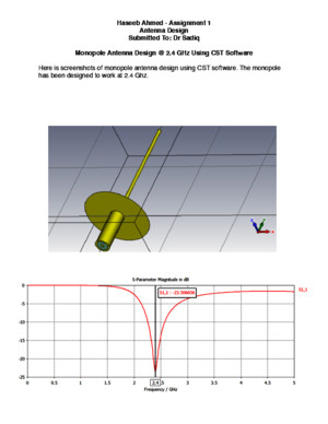
Progress In Electromagnetics Research C, Vol 53, 177–186, 2014 Dual Band Notched UWB Monopole Antenna Using EmbeddedOmega Slot and Fractal Shaped Ground Plane Balaka Biswas 1, * , Rowdra Ghatak 2 , Anirban Karmakar 3 , and Dipak R Poddar 1 Abstract —This paper presents the development of an Ultra Wide Band (UWB) monopole antennawith dual band notch characteristics Modified crown-square shaped fractal slots in the ground-plane areimplemented to enhance the impedance bandwidth to around 58% as compared to conventional squaremonopole antenna without slots Impedance bandwidth of the proposed antenna is approximately 114%with Voltage standing wave ratio (VSWR) < 2 In addition to this, two omega-shaped (Ω) slots havebeen incorporated in the radiating patch to render band-notch characteristics centered at 55GHz bandassigned to IEEE80211a and HIPERLAN/2 as well as X-band for satellite communication centered at75GHz band Measured antenna gain is stable over the entire UWB region except at the notch bandsRadiation pattern of the antenna show that the proposed antenna exhibits nearly monopole like E planeradiation patterns and omni-directional H plane radiation patterns throughout the band A fabricatedprototype is developed with close agreement between simulated and measured results 1 INTRODUCTION Over a decade ago, the Federal Communication Commission (FCC) allocated the frequency range of 31GHz to 106GHz [1] for Ultra Wide Band (UWB) communication with the power spectral densityof − 41 3dBm/MHz Design of components for ultra-wide band system remains a challenging taskowing to the wide impedance bandwidth Maintaining the 7500MHz bandwidth with compact circuitsize is the main aim of the research work in this field Several methods have been implementedto improve the bandwidth of planar monopoles based antenna topology [2,3] However, thereexist some different narrowband systems in the UWB frequency range such as 515–5825GHz bandassigned for IEEE80211a and HIPERLAN/2 and 735–775GHz band for downlink of X-band satellitecommunication systems In recent years different strategies have been investigated to reject suchfrequencies [4–6] Introducing slot is a very popular and easy approach in this regard Various shapedslots have been implemented in the ground plane [7], and radiating patches [8–12], to filter out theunwanted frequency bands Beside this slot geometry, use of split ring resonator [13], Hilbert curves [14],are another way to notch out the desired frequency band Stretching the impedance bandwidth beyondthe specified UWB range is another challenging task for any RF engineer Numerous topologies havebeen reported for this purpose, like M-shaped strip on conductor backed plane [15], inverted L-shapedslit and inverted U ring shaped slot in the ground plane [16], by using modified penta gasket Koch(PGK) in [17], T-shaped notch [18] in the ground plane and in [19] by cutting a rotated T-shaped notchin the ground plane and also by inserting rotated T-shaped parasitic structure, again in [20] by cuttinga pair of L-shaped slots on the radiating patch and also by adding a pair of L-shaped conductor backedplane in the ground plane the bandwidth is increased Received 7 July 2014, Accepted 26 September 2014, Scheduled 1 October 2014 * Corresponding author: Balaka Biswas (balakabiswasgmailcom) 1 ETCE Department, Jadavpur University, Jadavpur, Kolkata, India 2 Microwave and Antenna Research Laboratory, ECEDepartment, National Institute of Technology Durgapur, India 3 ECE Department, Netaji Subhas Engineering College, Kolkata,India 178 Biswas et al Fractal geometry has been often used to design multiband miniaturized antenna [21] The self similar and space filling property of fractal geometry [22–26] increases effective electrical length toreduce the size of the antenna and enhances bandwidth by bringing multiple resonances closerThis paper mainly focuses on two different issues in the development of UWB antenna One is todesign a compact UWB monopole antenna with improved impedance bandwidth and the other is tohave band notch characteristic at two different frequencies The novelty lies in the application of fractalgeometry in ground plane to increase the bandwidth and reduce the size of antenna This stems from thefact that resonance characteristics of coplanar waveguide based UWB monopole antenna depends alsoon the shape and size of ground plane However, this has not been investigated extensively This paperattempts to explore this issue by using crown-square fractal technology in the ground plane by which114% impedance bandwidth is achieved Omega-slots have been introduced in the patch close to eachother to bring about band notch characteristics In comparison to [17] the proposed antenna providesbetter bandwidth performance and in comparison to [4–6], it provides strong radiation attenuation atthe notch bands However, in literature various antennas are reported with dual, multiple band notchcharacteristic [9,13] but their gain performances are low with respect to the proposed antenna Tocomprehend the operation of the band rejection mechanism of the slots and radiating element a lumpedelement equivalent circuit model is developed Rest of the paper is arranged as follows Detailed antennadesign with parametric studies is given in Section 2, followed by results and discussion in Section 3 withconclusion in Section 4 2 ANTENNA DESIGN AND PARAMETRIC STUDY21 Basic Antenna Design The proposed antenna is fed by a Co Planar Waveguide (CPW) transmission line of 50Ohm as shownin Figure 1(a) It is realized on an FR4 substrate of ε r = 4 4, h = 1 6mm having loss tangent of tan δ = 0 02 The basic antenna structure consists of a square patch whose dimension is determined byquarter wavelength at lowest resonant frequency as given by (1) f L = c 2( L p + W p ) √ ε eff (1)where f L is the lowest resonant frequency at 36GHz, c the speed of light in free space, ε eff the effectivedielectric constant, and L p and W p are the length and width of the patch, respectively The squarepatch has a very compact dimension of ( L p × W p ) 13 × 13mm 2 and upon including substrate the overallantenna dimension is L sub × W sub 36 7 × 28mm 2 22 Fractal Slot Design on Ground It is a common observation in CPW-fed monopole antenna that the radiation and resonancecharacteristics depend on the size of the ground plane Therefore, to explore the effect by using fractalshapes in the ground plane a crown-square fractal was introduced [27,28] in each of the coplanar groundplanes which resulted in altered current path and subsequently a change in resonance characteristicsThis led to 58% bandwidth enhancement in comparison to conventional square monopole antenna withno such fractal slots Figure 1(a) shows the antenna structure followed by ground fractal in Figure 1(c)The modified crown square fractal is created by etching a rectangle and there after adding a squarefrom the middle portion of rectangle in an iterative manner as shown in Figure 1(b) In the first iterationof fractal, a = 10 7mm, b = 8mm and a/b = 1 33 where a and b are the sides of rectangle which isetched from the ground plane, and a square with a side length b is inscribed into the middle portion of the rectangle This is called first iteration In the 2nd iteration, another rectangle of 06 times of a and06 times of b is etched in the middle of the 1st iterative square The sides of rectangle are indicated by c and d , where c = 6 44mm and d = 4 8mm and maintain the ratio of c/d = 1 33 Again, the squareof same side length as d is inscribed in the middle of rectangular slot Same type iterative procedurefor fractal has been taken for further stage In this paper up to 4th iteration is shown as the designbecomes quite complicated, and fabrication is no longer feasible with higher iterations Progress In Electromagnetics Research C, Vol 53, 2014 179 0th 1st 2nd 3rd 4thIteration Iteration Iteration Iteration Iteration (a) (b)(c) (d) Figure 1 Proposed Antenna geometry (a) Antenna structure (b) Fractal algorithm (c) Fractal onthe ground plane (d) Omega shaped notch on the radiator Figure 2 Simulated results of proposed antenna with respect to each iteration Table 1 Bandwidth improvement in different iteration Iteration no Lower cut off Frequency (GHz)Upper cut off Frequency (GHz)Bandwidth(GHz)% of BW improvementwith respect to thezeroth iterationZero 330 850 520 -1st 325 870 545 480%2nd 321 890 569 940%3rd 315 90 585 1250%4th 310 1130 820 5769% As the iteration of fractal slot on the ground plane increases, matching improves at the upperband edge, and as a result, the overall bandwidth increases by 58% in comparison to the simple squaremonopole antenna The comparison is shown in Figure 2 and presented in Table 1
Recommended